The focal point of this page is the set of sheet-to-tiller self-steering gears developed for 1965 Pearson Ariel hull #330, "Augustine."
No representation is made that these systems will work on your Ariel or on any other boat, but my research tells me that the sheet-to-tiller steering information on this page will likely be of assistance in designing sheet-to-tiller applications on other Ariels and on other types of sailboats that utilize tillers for steering.
No representation is made here that it is safe to lash the tiller or utilize self-steering gears of any sort when sailing in close quarters, or while not on watch.
There is an inherent danger in venturing forth in a boat of any design. It us particularly dangerous to do so alone. The information on this page is not an endorsement of single-handed sailing.
The chief dangers of sailing are falling overboard and running into something solid, but there are many others. These dangers are greater when you venture forth alone. Single handing is a dangerous thing to do.
How sailing relates to driving to work on the freeway I am not sure, but before you take an automobile out for a drive, you must qualify for a motor vehicle license to operate that automobile on the public highway. Although not all state agencies require that you qualify to command you own vessel for recreational use, do yourself a favor: Before you venture forth in a boat of any type, call your local Flotilla of the United States Coast Guard Auxiliary and take one of their basic boating courses and their Advanced Coastal Navigation Course. Find a local Coast Guard Auxiliary Flotilla on the USCG Auxiliary National Web site. Regardless of how long you have been sailing, you will learn much about boating safely in a Coast Guard Auxiliary course. And if all goes well, you will meet some nice sailors and sailor wanna-bes there, and with any luck some of them will want to go sailing with you. Sailing with a friend is much safer than sailing alone.
Remember that a friend can maintain a look-out while you are below at the navigation table or fixing lunch. A friend who knows how to sail will be able to turn your boat around and come back for you if you fall overboard. If you are alone when you fall overboard with your tiller lashed or connected to a self steering gear, self-steering vane or auto pilot, your boat will happily sail away into the sunset while you wave goodbye.
If you install a sheet-to-tiller self-steering system on your boat, your boat will become conscious of (sensitive to) the force of the wind on its sails. Although a boat as heavy as an Ariel might sense a slight change in its weight distribution when you fall overboard, it will in all likelihood remain on course.
The sheet-to-tiller self steering system that you install on your Ariel will not make your boat conscious of (sensitive to) your presence. Indeed it does just the opposite. If you fall overboard while sailing alone with your self-steering gear engaged, your boat will sail very well without you on board. A life jacket, AND a harness, AND secure places to attach that harness, AND a reasonable way to climb back on your vessel at sea are all necessities for the single hander. Life jackets AND harnesses are highly recommended for all crew members when on deck even even fully crewed. They are even more important when crew members are on deck forward or aft of the cockpit. A waterproof VHF radio and personal locator beacon (PLB) in your pocket are also excellent safety devices, and are highly recommended. Cell phones do not work when wet. A jackline system, with boarding ladders is portrayed on our Augustine Photo Page..
So if you are thinking of single-handing and your name is not Joshua Slocum, don't do it. If your name is Joshua Slocum, take advantage of state of the art safety equipment before you venture forth alone.
The Pearson Ariel is a wonderful little boat. Although only 25 ft, seven inches in length, 8 ft in beam, and with a water line length of only 18 ft, six inches, she was designed to dig her rail into the sea and run faster than her nominal hull speed. When well rigged and well balanced, this full keel sloop will sail a steady track for miles when close hauled under reasonable conditions with her helm lashed..
The addition of an auto-pilot or a self-steering vane will greatly enhance the boat's ability to stay on course, but both of those systems require compromises. A self-steering vane ads weight and windage to the counter stern aft of the rudder. Installation of an auto-pilot requires power generation. Pearson Ariels were equipped with either an inboard engine, or with an outboard well. The outboard well was the most common. Power generation on outboard models, and even on the inboard models can be an issue on longer trips. Auto pilots steer a compass course that will not maintain a constant relationship with wind direction when the wind shifts unless the autopilt is equipped with a vane. Both self-steering vanes and auto-pilots require a significant financial investment.
Sheet-to-tiller steering systems offer an alternative. The design and application of the self steering gears on this page are based on the pioneering work of John Letcher as documented in his book, Self Steering for Sailing Craft, International Marine Publishing Company, 1974; and some sketches and suggestions included in Tony Heisel's book, A Manual of Single Handed Sailing Arco Publishing Inc., 1981. I also relied heavily on the on-line resources including the pages produced by John Ward and Al Gunther. See our resource section below for more information on where to obtain a copy of John Letcher's book and also for a list of on-line resources for sheet-to-tiller steering.
The sheet-to-tiller self-steering gears featured on this page were developed by combining systems designed by others, with the results of self-steering experiments that I performed on my Ariel. If you adapt any of these systems for your boat, you will no doubt find it desirable to make further modifications and innovations.
I have not reproduced the fine analysis of why sheet-to-tiller steering works. If you read John Letcher's book, you will learn all you need to know about the physics behind sailboat stability and sheet-to-tiller steering.
Suffice it to say in Mr. Letcher's words that mainsheet-to-tiller self-steering, "capitalizes on the boat's natural stability, and while close reaching and uses the mainsheet tension to adjust for change in the wind force. A control line from the tiller passes through a block on the weather side of the boat and then is bent to the standing end of the mainsheet tackle so it puts a bend in it; this provides the weather helm. The pull of the control line has to be partly balanced by elastic to the lee coaming."
"jib sheet tension balanced with elastic is used to provide the weather helm.... With the sails trimmed properly, the jib sheet tension is extremely sensitive to the apparent wind direction, If the boat bears away a little, the jib loses drive by stalling and by moving into the wind shadow of the other sails; also the apparent wind velocity decreases. (By the time the wind is about two points on the quarter, the jib is empty of wind and the sheet falls quite slack.) Then the elastic pulls the helm down to send her back on course. On the other hand if she luffs a little, the jib finds itself in clearer air, and a more favorable angle of attack, with a stronger apparent wind, and it starts pulling very hard on its sheet. So this hauls the helm up and she has to go back on course.. This action is so powerful that in practice the course steered is very precise even in a considerable seaway."
So if those quotes whet your whistle for more information on the "whys" of sheet-to-tiller steering, then buy a copy of John Letcher's book Self Steering for Sailing Craft. You can purchase this book from your local independent bookstore or use the link below to purchase it from Amazon.com.
On "Augustine", my system for self-steering on headings ranging from close hauled to a beam reach is a direct adaptation of John Letcher's system from the mainsheet to the tiller and a direct piracy of John Ward and Al Gunther's design for the leeward elastic device, which was in turn based on Letcher's earlier work.
Mounting two cam cleats on the tiller is not my concept. That idea is documented on John Ward's Self Steering page page, but I found it difficult to make fine tuning adjustments with the cam cleats. I also found the lines difficult to release from the cleats when they were under tension. So, I added a vang to the system to solve these problems and to permit adjustment of the steering gear from the companionway.
I was loath to drill more holes in my tiller, but I wanted a couple of cleats to secure control lines, so I designed the steering gear control box box on Augustine to utilize two existing vertical holes in the tiller. I mounted the cam cleats to the steering box, thereby spreading the load of the control lines over a larger section of the tiller, and making the whole system removable.
My jib-to-tiller self steering gear is heavily hybridized, and multi-faceted. In one version, I built a cam lever to connect the jib sheet to the tiller. This device is based literally on John Ward and Al Gunther's adaptation of John Letcher's cam lever design.
Instead of using this cam while single handing, I more often use a device of my own design to transfer a portion of the jib sheet tension to my tiller, but the science and concept behind the design is pure Letcher, with a twist from Tony Heisel that is a near perfectly adapted to the high coaming boards on the Ariel. That twist is taking a quarter turn around the leeward jib sheet winch before securing the sheet on the windward winch. That innovation is "near" perfect, because the winch barrel is not a frictionless surface. Although the resulting sheet-to-tiller gear could maintain a more-or-less steady average course, it was subject to wide over-corrections. Therefore I developed a further refinement to Tony Heisel's conceptual drawing by designing and building a device that permitted me to attach a block to my leeward winch that placed the block high enough to clear the coaming board. This refinement is discussed in the Jib-to-Tiller Steering section below.
The cost of building your own sheet-to-tiller system is low. The installation is impermanent, so you can remove and store the equipment below when you are not using it. Few of any structural changes to your boat will be required. I made no structural changes to Augustine whatsoever. I was able to use existing winches, cleats, pad eyes, and two existing vertical holes in my tiller. My set of steering gears (with the exception of the self steering control box, cam lever, and leeward winch device fit into two small boxes that sit on the shelf above the starboard settee.
The best news is that installing self steering gears on your boat will give you a new sense of confidence and freedom. I find that when I am offshore with my gears in use I am free to spend more time below at the navigation table or fixing meals. I am free to work on the boat while under sail, and I am free to leave the tiller to take photographs, or to go forward for extended periods of time on any heading. Dropping the jib or changing head sails used to be a chore when I was sailing alone, but my mainsheet-to-tiller self-steering gear now permits me to drop and bag the jib or change sails while maintaining a steady course.
published by Arco Publishing Inc. New York 1981.
On-line Information
- Sheet-to-Tiller Self Steering - John Ward with information and photos by Al Gunther
- http://www.jsward.com/steering/index.shtml
- The Oar Club - Self-Steering Gear
- http://www.oarclub.org/page22.html
- Self Steering Sheet-To-Tiller and Servo-Pendulum Windvane
- http://www.todspages.net/SSa-SelfSteering.html
- Cruising Resources Sheet-to-Tiller Steering
- http://www.cruisingresources.com/Full_Sheet-to-Tiller_Steering.asp
- Self Steering for the Flicka:
- http://www.geocities.com/Yosemite/Forest/2727/flicka_selfsteering.html
- The Steersman - Jib Sheet to Tiller Self Steering Gear
- http://www.steersman.net/index.htm
 Back To The Top
Early Experiments
Mainsheet-to-Tiller Prototypes
The wisdom in John Letcher's book and on the above referenced websites dealing with this topic supports using mainsheet tension for a mainsheet-to-tiller steering gear for sailing on headings from close to the wind to a little less than a beam reach.
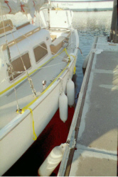
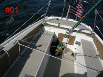
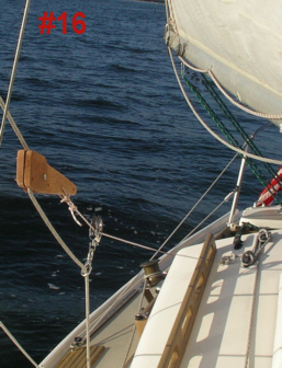
In photo #1 is my first attempt at a mainsheet-to-tiller-rig for close-hauled sailing. I had not yet cut any lines or surgical tubing, so I had to tie a few temporary knots and make some adjustments as I went. (Ever tie a bowline or a half hitch in surgical tubing?). Nonetheless, this crude system worked well while beating in variable wind and swell in the ocean with working jib and full main. I was having considerable success (as in sailing close hauled for miles in modest open ocean swell with winds to twenty plus mph).
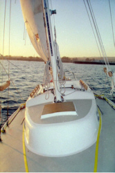
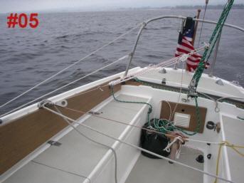
Photo #5 shows a more sophisticated prototype for the mainsheet tension driven gear, which also proved to be very effective for headings from close-hauled to almost a beam reach. This gear moved quickly from prototype to fully functionally system in near-final form. It proved the effectiveness of the vang concept, and demonstrated the effectiveness of my home-designed steering control box. The steering control box is also used with the jib sheet-to-tiller gear. The mainsheet and jibsheet systems both feature a weather-side vang (block and tackle), and a lee-side elastic device that permits one, two, or three strands of surgical tubing to be employed depending on heading and wind strength. In photo #5, a single strand of surgical tubing is shown. When the photo was taken, I had not yet built the four strand elastic device shown in the Equipment section below.
Regarding the use of Surgical Tubing:
"Don't use bungee cord" is the prevailing logic. In his book, John Letcher effectively explains the difference between the linear stretch curve of surgical tubing verses the parabolic stretch curve of bungee cord. So, use surgical tubing. The tubing used in the photo below is 3/8 inch OD (outside diameter). Note: Medical supply folks sell their surgical tubing by inside diameter, but self-steering advocates describe it by outside diameter. Also note that many writers have documented the UV sensitivity of surgical tubing. So use sunscreen on yourself, store your surgical tubing below when not in use, and have a spare elastic device on hand.Some authors recommend dark colored surgical tubing. I used plain old ordinary everyday surgical tubing.
Jibsheet-to-Tiller Self-Steering Prototypes
Various writers recommend using jib sheet tension to self steer on headings from a beam reach to a broad reach. My experiments make me support this recommendation. This is a more temperamental system than the mainsheet-to-tiller gear. Some writers recommend employing a jibsheet-to-tiller gear only on longer tacks. In 20+ mph winds and a lumpy sea, going forward on the lee side of a Pearson Ariel while alone to engage a cam lever is an interesting exercise. There are other alternatives to the cam lever that make the use of jibsheet-to-tiller gears practical on a Pearson Ariel for shorter tacks. Later experiments confirmed the feasibility of a jibsheet-to-tiller gear that can be installed from the cockpit for either short or long tacks. See the Equipment and Jibsheet-to-Tiller sections below.
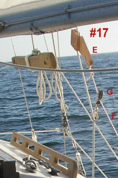
The cam lever "E" shown in photo #17 is a prototype made of scrap redwood and a few stainless steel fasteners.
John Letcher provides schematics for using the cam lever and/or a "fools purchase block and tackle" arrangement to lighten the load of a direct jibsheet-to-tiller gear. In using the cam lever, you leave the jib sheet on the leeward winch, but the line running from the cam lever to the tiller can too easily take the entire load of the jibsheet if the jib is slacked off. This could be a bad thing depending on the load and strength of the cleats and blocks supporting your self-steering gear.
I find that use of a vang within the cockpit to transfer a portion of the jibsheet load to the tiller is a safer and easier system to use than the cam lever system. The vang makes minor adjustments easy, facilitates remote operation, permits jib sheet adjustments without overloading the gear and tiller, and allows me to avoid crawling out on the leeward deck to install the cam lever while under sail.
Again, the various jib sheet-to-tiller gear alternatives use the exact same surgical tubing device on the lee side that is used for the mainsheet-to-tiller gear.
I discovered that once I made up a four strand surgical tubing device and purchased a few Garhauer series 25 blocks, I could use them all for both the main-to-tiller and jib-to-tiller gears.
To build a similar system, you need surgical tubing, Dacron line, some blocks, some snap hooks, two cam cleats and a few pieces of wood to build a steering control box or another way of attaching lines to your tiller. You also need some mechanism (cam lever or vang system) for transferring part of the jib sheet pressure to your tiller for the jib-to-tiller gear. The cam lever can be built of wood and fasteners like my prototype, or of wood, two sheaves and half a cam cleat as John Letcher diagramed in his book.
I have four) Garhauer Series 25 low friction ball bearing stainless steel blocks in my set-u,p and I am using 3/16 and 1/4 inch Dacron line. Low friction blocks are very important. The steering control box incorporates two cam cleats, but again, these cam cleats could be directly attached to the tiller. You can also just tie your lines around the tiller. I did that for a while and it works, but that makes adjustment difficult. See photo #01 above. Alternatively, as John Letcher did on his boat, you can run two bronze or stainless pins horizontally through your tiller to serve as cleats.
If you do use cam cleats on your tiller or on a steering control box, be careful of the angle of the approach into those cam cleats (over the tiller and straight down) The angle of approach can be a more serious problem if you are using a smaller diameter 3/16 control line with no vang. Larger ( 1/4 inch or larger) line is less problematic in this regard. Too much tension on the control lines, and you will have to work too hard to free the lines. This is one reason that I decided to use a vang on both the mainsheet-to-tiller and jibsheet-to-tiler gears.
Back To The Top
Sheet-To-Tiller Self-Steering Equipment
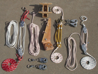
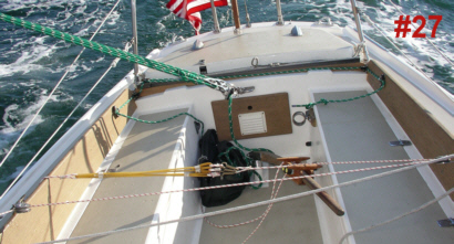
The whole kit and caboodle appears in photo #07. This array of lines, blocks and other equipment is most of the equipment that it takes to accomplish both mainsheet-to-tiller and jibsheet-to-tiller steering on a Pearson Ariel. I continue to work on refinements. These refinements, if successful, will be posted on this page from time to time. The wooden cam lever at the center of the photo is redundant to the red colored line and tackle at the left side of the photo, but both are shown in this photo anyway.
Photo #07 does not show a more recently developed winch-mounted turning block holder/oar lock device designed to reduce friction on one jibsheet-to-tiller steering gear configuration. That device is shown later in this Equipment section.
Mainsheet-to-Tiller Gear Equipment
Photo #54 shows the equipment used for mainsheet-to-tiller steering.
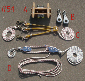
A. The teak self steering control box slides over the tiller and attaches to the tiller with two vertical bolts, washers, and wing nuts. The two cam cleats hold the steering lines.
- Box built of teak to fit the tiller
- Two cam cleats sized for line to be used
- Box (external) 2 7/8" wide X 2 1/4" high X 7" long
- Box (internal) 1 3/8" wide X 1 3/4" high
B. Two Garhauer Series 25 blocks with shackles attach to the bronze cleats on the top of the coaming boards just aft of the jibsheet winches .
C. Four strand elastic device made from surgical tubing, waxed small stuff, and Dacron line. Used on the leeward side from mooring cleat to tiller-mounted steering control box cam cleat.
- Three #3 snap hooks
- 3/8 inch external diameter surgical tubing 4 feet
- red flecked 1/4 inch Dacron line (inboard end) 4 feet
- red flecked 1/4 inch Dacron line (outboard end) 4 feet
- Waxed small stuff
I used John Ward's exact measurements and specifications to make up my surgical tubing elastic. The surgical tubing device is shown in action in the Mainsheet-to-Tiller and Jibsheet-to-Tiller sections on this page.
D. The mainsheet-to-tiller control line runs from standing part of mainsheet tackle through a weather-side Series 25 block "B" to a cam cleat on tiller mounted steering control box "A". The fall on the vang (block and tackle) shown here is used to make adjustments in tension. The vang is:
- Ronstan 29 mm Fiddle block with jam cleat #RF187
- Ronstan 29 mm Fiddle Block #FR186,
- Ronstan Becket Shackle #RF807
- blue flecked 1/4 inch Dacron line 18" (mainsheet end)
- blue flecked 1/4 inch Dacron line 7 ft (tiller end)
- red flecked 3/16 inch Dacron line 17 ft
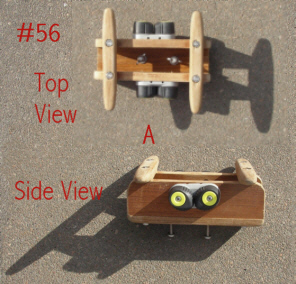
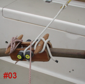
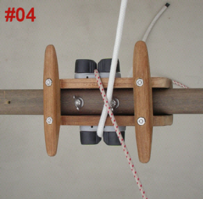
The steering control box "A" (photos # 56, #03 and # 04) is sweet...at least until one of those hand-made teak cleats jabs you someplace tender. The cleats like to chew on the inside of thighs. Actually, all you need are a pair of cam cleats mounted on the sides of your tiller, but one of my design criteria was not to drill any more holes in my tiller. The lines running to the steering control box in photos #3 and #4 are part of one of the early prototype gears. As shown in the photos, that white line is connected to a single strand of elastic. Elastic device "C" with it's attached 1/4 inch Dacron lines later replaced this white line.The red flecked line in photo #04 is 3/16 inch Dacron line, which proved to be too thin for use in the cam cleat without binding.
The steering box quickly attaches with two wing nuts. My reasoning in developing this design is that I use these devices because I want to let the boat steer itself for hours and hours and hours...or at least for quite a while, and during that quite-a-while, I am not in the aft part of the cockpit. Although my design is space-intensive when in use, it can be put away below and does not crowd the cockpit or interfere with other functions when not in use.
The problem with the teak cleats on the steering box is that when you are tacking, you have to slide in behind the box. Those teak cleats are more than little intimidating, even if they are useful for coiling excess control line tails. It is quite easy to slip back on the lee side of the tiller when the gear is in use, but some experience as a spider would be useful before you climb through this web to reach the windward side of the tiller when beating in strong wind conditions. If you don't like the teak cleats on the steering control box, leave them off. The only debit will be excess line that cannot be secured to a cleat.
Other systems that I have reviewed have used cam cleats on the tiller, but I found making fine adjustments in heavy wind to be rough with just those cleats. The lines that run through them can be under considerable pressure. Using a vang in control line "D" makes this system purr. On the mainsheet-to-tiller gear, I use vang "D" not to reduce the line pressure on the tiller, but instead to allow me to make fine adjustments to the system with "fingertip control." On the jib-to-tiller gear, I use vang "H" to transfer a portion of the jibsheet tension (load) to the tiller, and also to make fine adjustments to the system.
Jibsheet-to-Tiller Gear Equipment
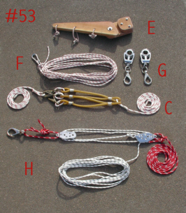
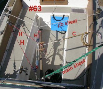
Photo #53 shows the equipment used for jibsheet-to-tiller steering. Steering control box "A" shown in photo #04 is also used in this system.
E. The cam lever in photo #53 is applied to the jibsheet forward of the first turning block in one alternative method of setting up a jibsheet-to-tiller steering gear. The cam lever "E" is not used with the jibsheet control line and vang shown in this photo as "H".
Cam Lever "E" is a prototype built of redwood with stainless steel fasteners. Use light wood, since this device can drop to the deck. Three wooden pieces:
- Lever Arm is 14'' X 3 3/4"
- Other two pieces are 3 1/4" X 5 1/2 " and 3 1/4" X 5 1/2"
- Three short strands of 3/16 inch red flecked Dacron line tied in loops with becket bends and seized with waxed small stuff.
F. This Dacron control line attaches to the cam lever and runs aft through the leeward series 25 turning block "B" portrayed in photo 54 above, which is attached to the coaming board cleat aft of the leeward jib winch. Control line "F" then runs across the cockpit to the windward series 25 block (also a block "B"), and finally to the cam cleat on the tiller-mounted steering control box "A". Control line "F" is not used with vang "H" shown in this photo.
- Jibsheet cam lever to tiller control line: red flecked 1/4 Dacron line 29 feet.
- One carbiner
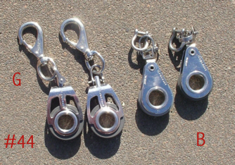
G. Two additional Garhauer Series 25 blocks are shown in photo #44. These are the open faced models labelled as Block "G". Although I would have preferred swivel blocks, these work adequately for the application. With the exception of the lack of the swivel feature, they function exactly the same as closed face models (Block B). These blocks are attached to snap hooks (a low cost alternative to a snap shackle for low load uses.) In one jibsheet-to-tiller gear configuration, I use these blocks without the snap hook. In that configuration I have labelled these open faced blocks as Block "K" to indicate that they lack the snap hooks. Block "G" and block "K" are indentical, but block "K" lacks the snap hook.
One of these blocks "G" is used with vang "H", and one is used with the cam lever "E". Although they could be substituted for Block "B", Block "B" is already in place for mainsheet-to-tiller gear use and is left in place for the jibsheet-to-tiller gear. Block "G" is used to secure one end of vang "H" to a pad eye at the aft end of the cockpit. The block is connected to the pad eye using the snap hook.
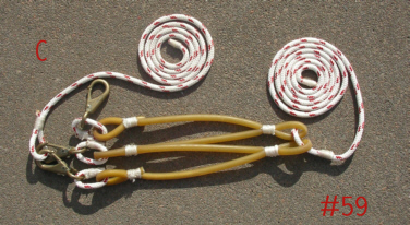
C. Four strand elastic device shown in in photos #54, #53 and #59 is made from surgical tubing, waxed small stuff, and Dacron line. See mainsheet-to-tiller equipment section above for measurements. Used on the leeward side from mooring cleat to tiller mounted steering control box cam cleat. Photo #53 shows all four strands of the device engaged using all three snap hooks (one double and two singles). Photo #59 shows three strands engaged with two snap hooks (one double and one single).
In the first version of the four strand elastic device that I built in 2004 (shown in photo above), the seized surgical tubing loops were not reinforced. I discovered that this led to rubber fatigue and in the loops due to excessive stretching in the end of the loops. To remedy this problem, the second generation built about five years later was modified. This later model is not shown on this web page, but looks the same superficially. The modification consists of inserting some pieces of braided Dacron yacht cord into the surgical tubing so that each loop (the entire loop) is reinforced and will not stretch. Each of the five (5) pieces of Dacron cord is slightly longer than the loop into which it is inserted. Any of portion of the Dacron cord that does happen to extend beyond the loop does not impede stretching of the tubing since the loop has been seized, capturing only the portion of the Dacron cord inside the loop. With this modification, the tubing in the loop only stretches to the degree that the Dacron cord stretches. So you might want to add five short pieces of Dacron cord to your materials list.
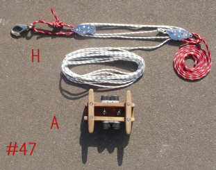
H. Vang "H" shown in photos #53 and #47 is used to transfer a portion of the jibsheet tension from the jibsheet to the tiller. I could also use this block and tackle (vang) in place of the mainsheet-to-tiller control line vang, but one end of the mainsheet control line must be shorter. Also, since it is possible to apply the jibsheet-to-tiller gear before disengaging the mainsheet-to-tiller gear when changing course from close hauled to an off wind course it is convenient to have two separate vangs.
Jibsheet control line vang is:
- Ronstan 29 mm Fiddle block with jam cleat #RF187
- Ronstan 29 mm Fiddle Block #FR186,
- Ronstan Becket Shackle #RF807
- red 1/4 inch Dacron line 26" (snap shackle end)
- red 1/4 inch Dacron line 11 ft (tiller end)
- green flecked 3/16 inch Dacron line 17 ft
- one #3 snap shackle
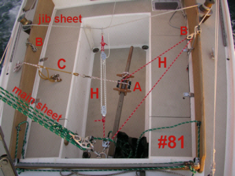
After taking a quarter turn around the leeward winch or alternatively through a winch-mounted block, the jibsheet runs transversely across the cockpit where it is wrapped twice around the windward jib sheet winch and secured to a cleat. The jibsheet control line with its integral vang "H" is clipped using a snap hook onto the midsection of the transverse jibsheet as the jibsheet runs between the two winches. The control line on other end of the vang runs from the vang through block "G", which is clipped using a snap hook to a pad eye on the aft bulkhead of the cockpit, and then "H" runs forward though windward-side coaming-board-mounted Block "B" pictured in photo #44 and #54 and finally to a cam cleat on the tiller-mounted steering control box. The fall from this vang is used to make adjustment in tension. In photo #47, vang "H" is shown with steering control box "A". Again this vang is not used with the cam lever "E". The cam lever "E" has its own control line "F".
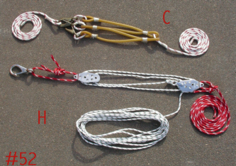
In photo #52, the control line "H" with integral vang is shown with elastic device "C". The longer (free) end of the line running from vang "H" runs from the vang aft to block "G", then to windward side series 25 block "B", and finally to the tiller-mounted steering control box The elastic device "C" is attached to a leeward side mooring cleat.
Use of control line "H" with integral vang in lieu of the cam lever device "E" provides a jibsheet-to-tiller gear that can be installed from the relative safety of the cockpit, and one that will facilitate quick disengagement and uncomplicated adjustment of the jibsheet tension.
Reducing Friction in Your Jibsheet-to-Tiller Gear
The black cylindrical devices shown in photos # 102 and #103 below are dual purpose devices made of four (4) inch ABS pipe and fittings. They were designed to accommodate a series 25 block to reduce friction in the jibsheet-to-tiller self steering gear, and also to hold oarlocks for 11 foot Carlisle Sweeps. These devices place a block "K" in the correct position to reduce friction in the jibsheet-to-tiller gear. A well positioned block "K" is an improvement over using the leeward winch as a "fairlead" for the jibsheet as the jibsheet travels up from the leeward side-deck-mounted jib track to the leeward winch on its way across the cockpit to the windward winch where the sheet is secured. This is an improvement over making a quarter turn around the leeward jib sheet winch because it reduces friction. Nothing will kill a sheet-to-tiller gear faster than friction.
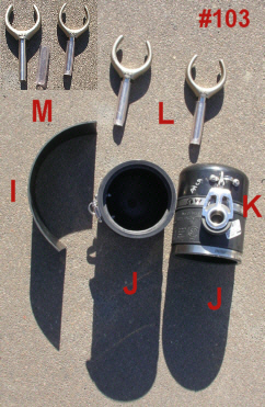
The device in photo #103, is made from:
- Shown as "J": One four inch length of four (4) inch ABS pipe
- Also shown as "J": One ABS/SDR coupler for four (4) inch pipe with two hose clamps
- Also shown as "J": One end cap for four (4) inch ABS pipe with hole drilled in center to accommodate an oarlock. (the hole is not necessary unless oar locks are part of your plan.
- Shown as "I": One shim made of 1/8 inch neoprene cut to fit internal diameter of the 4 inch ABS pipe section.
- Shown as "M": Sleeve made of 5/8 inch clear tubing, with bevelled end to facilitate a tight fit into the winch handle slot on the jibsheet winch. (not necessary unless oarlocks are part of your plan)
- Shown in photo #102 as "N": one padeye and fasteners (bolt, two washers and lock nuts). The series 25 block will attach to the padeye. The padeye fasteners will hold the end cap onto the ABS pipe, and could also be used to secure the 1/8 inch thick neoprene shim "I".
- Shown as "K": One series 25 ball bearing block (also pictured elsewhere as block "G", however as "G" this block has an attached snap hook. As "K" it does not)
- Not shown here: A short Dacron line to tether the device to a pad eye or cleat. I used a piece of Dacron cord with a snap hook.This cord is attached to a pad eye used in my jackline system. The pad eye is located just forward of the jibsheet winch on the deck outboard of the coaming board
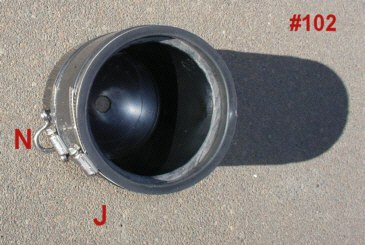
Photo #102 shows an internal view of the device "J". You can see the center hole in the end cap and the the four (4) inch ABS pipe within the coupler. The neoprene shim is not shown in this photo. The jibsheet winches on Ariel #330 are Barient #_. The diameter of the base is four (4) inches, but the diameter of the top of the winch is three and three-quarters (3 3/4) inches, hence the need to recess the ABS pipe in the coupler and also the need for the neoprene shim. If your winches are a different size, you will have to search for an alternative pipe size or thicker shim. The ABS pipe begins just above the first (lowest) pipe clamp on the coupler.
Whether or not you are going to utilize this device as an oar lock for sweeps, you will want to build two of these devices, one for each jibsheet winch.
More About The Cam Lever Alternative
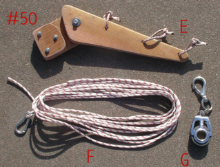
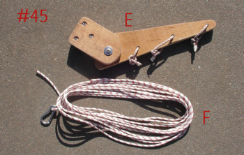
One alternative for a jibsheet-to-tiller gear is shown in photo #50 and #45. This gear uses the cam lever "E" shown in photo #50 and #45 and not vang "H" shown in photo #52 and not the winch-mounted device shown in photos #102 and #103. Line "F" in photos #50 and #45 runs from the cam lever though a leeward coaming-board-mounted block "B", then transversely across cockpit to windward block "B", and finally to the windward cam cleat on tiller-mounted steering control box.
Photo #50 shows the "cam" side of the cam lever and photo #45 shows the other side. The jibsheet-to-tiller control line "F" may be attached to any one of the three Dacron loops using its carbiner. The amount of tension desired determines which loop to use. Block "G" is attached to the jibsheet forward of the side-deck-mounted jibsheet track block using the snap hook. Jibsheet-to-tiller control line "F" is run through block "G".
Although this cam lever does work, providing a low friction method of transferring a portion of the jibsheet tension to the self steering gear, the design of the lever requires the person who is installing it to leave the cockpit in order to attach the cam lever to the jibsheet forward of the jibsheet track.
The person installing the lever must be on the leeward deck during installation and removal of the lever. Also, if you slack off on the jib, the entire load of the jibsheet may be transferred to the gear, unless the gear is first released or relaxed. This cam lever takes some time to install and to remove.
Back To The Top
Moving Beyond the Prototypes
Remember that these systems won't steer around other boats. They hold a course not by compass, but by the wind.
But while close hauled, I can go forward for hours when sailing alone if I want to do so, or go below to concentrate on navigation issues, make lunch, etc. Best of all, I can sit someplace dry (or less wet anyway) while Augustine sails herself. My role as Skipper then is not wrestling with the tiller, but tending the sails or the self-steering vang and elastic device from time to time, and focusing on keeping watch, navigation, and/or course planning.
A couple of additional words of caution:
1. Without a tiller in your hand, you tend to look around and not necessarily at the approaching swells. I was thrown across the cockpit by a swell that broke against the weather side of the hull, while I was focusing on something else. The wind was gusting above 20 mph and a three foot swell was running. That would not have happened if I had been at the tiller. Your automatic helmsman won't shout warnings to the crew.
2. More so than ever, wear a very short harness. My harness has a three and six foot tether. If you fall overboard while the gear is engaged, the boat will probably never round up. You might find yourself in the position of trying to climb back on board while beating at or beyond theoretical hull speed. Even if you are wearing a harness, this would be a difficult thing to do. Overboard without a harness, and you are just lost at sea. Also a life jacket and a waterproof VHF and/orPersonal Locator Beacon (PLB) in your pocket are both good ideas while sailing alone. The newer PLBs are equipped with GPS receivers, so that if they are activated, they will transmit your personal information, your latitude and longitude. Over time, your set and drift can also be calculated by rescuers.
3. Your self-steering system can't sense other boats, land masses, shallow water, buoys or hazards to navigation. When the wind direction changes, so will your heading.
4. Be careful about overloading the points (cleats and pad eyes) where you attach your self-steering blocks by transferring excessive tension from your jib sheet to your steering lines. If you utilize the cam lever option on your jib-to-tiller gear, all you have to do to transfer the full load of the jibsheet to the cleats and tiller is to slack off the jib sheet without first releasing your jibsheet-to-tiller control line.
Back To The Top
Mainsheet-to-Tiller Steering
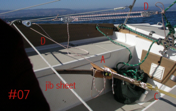
Shown in photo #07 is the windward side of the mainsheet-to-tiller gear, the tiller end of the elastic device "C", and the mainsheet to tiller control line "D" with its integral vang running through the windward Series 25 block "B" just aft of the jib winch to the steering control box on the tiller. The cleats on the steering control box "A" are used to secure excess line. The fall on the vang in this photo is just tucked over the coaming board. Normally I lead it forward and leave the end of the fall line in the cabin.
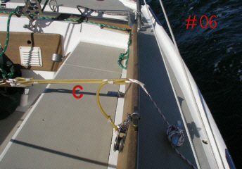
Shown in photo #06 is the leeward elastic device "C" secured to a mooring cleat on the outboard end and to the tiller on the inboard end with three strands engaged. The tiller end of this line is not shown in photo #06. The rest of the system is shown in photo #07
With the vang shown in photo #07, I can sit behind at the weather side of the cockpit behind the trunk cabin or in the companionway hatch and fine tune the rig if need be. Actually, if I were to reverse the vang, I could run the fine-tuning control line from the vang to a cleat at the aft end of the trunk cabin or even down into the cabin to a cleat. However, adjustments are few and far between, and I have not found a need to do this.
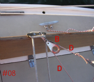
Photo #08 is a close-up of a series 25 block on the windward coaming board. The red flecked line is the mainsheet-to-tiller control line "D". Barely visible to the right is the end of the vang, which is integral with that line. The older blue flecked line is the jib sheet. For convenience, with or without the self-steering gear engaged, I usually wrap the jibsheet twice around the leeward jibsheet winch and then bring the bitter end over the the leeward coaming-board-mounted cleat and secure it there. I can then easily adjust jib tension from the weather side of the boat while at the helm. I don't usually need to use the winch handle to adjust the tension while sailing with the Ariel class jib.
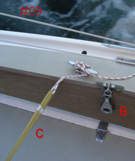
Photo #09 is a close-up of elastic device "C" as it runs over the coaming board and attaches to mooring cleat. Friction is not a factor on this section of Dacron line. The bronze coaming board cleat is also shown here. That cleat is just aft of the jibsheet winch. The series 25 block is attached with a shackle to the center of that cleat, but leaves the cleat functional for securing the jib sheet. A cleat hitch is used to secure the Dacron line leading from the elastic device"C" to the standard factory installed mooring cleat outboard of the coaming board.
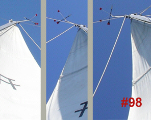
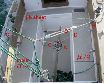
As shown in photo #98, the mainsheet-to-tiller gear will keep you on a steady course on headings ranging from a close reach to a beam reach under varying sea and wind conditions, but a shift in the wind direction means a shift in the course unless you adjust the gear. The long fall on the control line vang allows you to adjust the gear setting from the companionway hatch. I usually just toss the bitter end of that line through the companionway hatch as shown very faintly in photograph #79 so that it will be within reach whether I am in the cockpit or below.
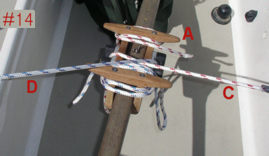 The steering control box"A" is shown in action in photo #14. The blue flecked line runs to the windward 25 series block "B" and back through the vang to the mainsheet.The red flecked line runs to the elastic device "C" on the leeward rail. The integral teak cleats offer places to secure the bitter end of the mainsheet-to-tiller line and the line leading to the elastic device. The teak cleats are also formidable weapons if your tiller becomes angry and decides to use them on you.
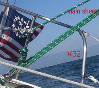
It is very important to put a bend in the mainsheet. Photo #32 shows the point at which the mainsheet-to-tiller control line "D" meets the standing part of the mainsheet. Make sure that you tie this control line to the standing end of the mainsheet tackle. Otherwise the knot could become caught in the block when you are adjusting the mainsheet. The line can be tied with a rolling hitch or another knot of your choice. When you tack, you will reconnect your mainsheet-to-tiller control line "D" on the weather side of the steering control box, but you do not need to untie it from the mainsheet. Simply slip the vang between the parts of the mainsheet tackle so that it will run fair and then reconnect it to the tiller after running it through the windward coaming-board-mounted series 25 block.
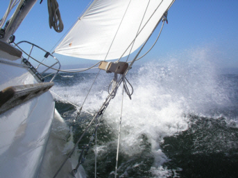
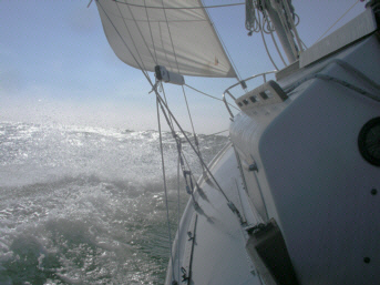
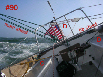
Images #79, and #90 below show the mainsheet-to-tiller gear in action. Don't forget that the mainsheet and jib sheet are very much part of the system. Correct sail setting is a critical part of setting the mainsheet-to-tiller gear. This is even more critical with the jibsheet-to-tiller gear.
Back To The Top
Jibsheet-to-Tiller Steering
There are two basic approaches to building a jibsheet-to-tiller gear:
- Capturing a portion of the jibsheet tension forward of the side-deck-mounted jibsheet track,
- See "The Cam, Lever Alternative" below, and
- Capturing a portion of the jibsheet tension aft of the side-deck-mounted jibsheet track.
- See "Using the Leeward Winch" and Reducing Friction in Jibsheet-to-Tiller Gears below
The Cam Lever Alternative
--Capturing Jibsheet Tension Forward of the Side-Deck-Mounted Jibsheet Track Block
In one option for transferring a portion of the jib sheet load from the sheet to the tiller, a cam lever can be used. This cam lever "E" is designed to transfer a partial load from the jib sheet onto a jibsheet-to-tiller steering control line "F", which is run through three blocks to the tiller.The cam lever does work. The cam lever shown in photo #19 is an intentional, if poorly executed, rip-off of the cam lever design on the wonderful sheet-to-tiller steering page:
http://www.jsward.com/steering/index.shtml
The above page is worth reading and following. It provides detailed directions for designing a sheet-to-tiller self-steering systems and an innovative approach to using surgical tubing in self steering systems.
Photo #17 below shows the cam lever in action on a port tack. As you can see from the photo, the cam lever is applied to the jibsheet in a manner that allows the cam lever to be utilized to capture a portion of the tension from the jibsheet forward of the side-deck-mounted jibsheet track block.
The cam lever is installed in the following order:
The jibsheet-to-tiller steering control line "F" is run through a "loose" series 25 block "G", which has a snap hook attached to it.
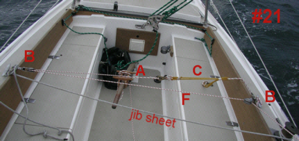
--The free end of the jibsheet-to-tiller self steering control line "F" as shown in photo #17, #21, and #22 is then run through the series 25 block "B" attached to the leeward coaming board cleat as shown in photo #21 below, then transversely across the cockpit through a series 25 block "B", which is attached to the windward coaming board cleat also as shown in photo #21, and from there to the the tiller-mounted steering control box"A", where it is led through a cam cleat on the box.Please note that photo #17 shows the gear on a port tack, while photos #21 and #22 show the gear on starboard tacks.
--The snap hook on the "loose" series 25 block "G" is then clipped onto the jibsheet forward of the leeward jibsheet track block. A little friction here is OK. Friction against the jibsheet-to-tiller control line is not OK. Clip the snap hook on the jibsheet, not on the jibsheet-to-tiller steering control line. So keep it in mind that the control line "F" runs through the "friction-free" block and the jibsheet runs through the clip.
--Clip the carbiner on the end of the jibsheet-to-tiller steering control line "F" to one of the three loops on the cam lever "E".
--The Cam lever "E" is then secured to the jibsheet forward of the side deck mounted jibsheet track.
--To hold the cam lever in place, some downward pressure is applied to control line "F" by the foolhardy crew member who elects to crawl forward onto the leeward deck to install this device. Pressure must be applied until the tiller end of the control line has been made secure and the line pulled tight in the cam cleat on steering control box "A". After that, the installed gear will provide the pressure to keep the cam lever in place on the jibsheet.
To remove this gear, begin by releasing the tension on control line "F" at the tiller slightly, and then by moving back to the side deck while maintaining manual tension on control line "F". Finally, when you are in position on the side deck, release downward pressure on the cam lever, remove the cam lever and the snap hook from the jibsheet. Try doing this with one hand for a special thrill. Remember that while you are doing this, the boat is no longer steering itself, unless you have employed another gear, another method of self steering, lashed the helm, or more sanely perhaps, unless you are sailing with a second crew member who can tend the helm.
Keep in mind that releasing all jib sheet tension can cause the jibsheet to shake off the cam lever. The cam lever will then either drop overboard or onto the deck. Installing a simple lock on the lever and/or other cam lever design improvements could solve this problem. in any case, a flailing cam lever is not a pretty sight. The cam lever shown in the photos is merely a quickly made redwood prototype. John Letcher's drawing of a similar device utilizes professionally made cam cleats and half of a sheave in lieu of the wooden parts shown in the photo.
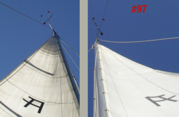
The side-by-side images of Augustine's mainsail while on a beam and broad reach in photo #97 demonstrate with the wind indicator the range of headings that this device can accommodate if the sails are adjusted properly.
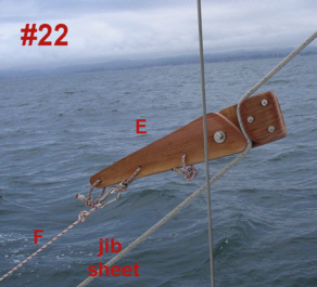
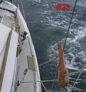
Cam lever "E" is shown in use while on a starboard tack in photo #22. Here you can see the bend placed by the lever on the jibsheet. The degree of bend will determine the amount of tension transferred from the jibsheet to the tiller through jib-to-tiller self-steering gear control line "F".
The bend on the cam lever is increased or reduced by adjusting the jibsheet-to-tiller control line at steering control box "A" on the tiller.
My chief concerns with use of this cam lever:
1. You don't want to let out the jib before you disengage the cam cleat on the side of the tiller steering control box. If you do, the full load of the jib may be transferred through the cam to the tiller. So, you need to relax steering control line "F" first, or perhaps disengage it completely at the tiller mounted steering control box until the jib has been reset, and then re-engage it afterwards.
2. You must crawl out onto the leeward side deck to apply the cam lever to the jib sheet between the jib clew and the side-deck-mounted jibsheet track block.
3. You cannot tack or jibe until you have removed the cam lever and snap hook from the jib sheet and disconnected the gear from the steering control box. After you tack or jibe, you must install the gear again on the opposite side of the boat.
Since other writers make use of similar cam levers, I assume that the shortcomings that I have observed are surmountable. I have built and tested this gear as documented in the photos, but I have not used it extensively due to my overriding concern with the safety of installing the gear from the side deck while sailing alone.
The remaining photographs in this section show the gear in place and working from several different views.
Back To The Top
The high coaming boards on the Pearson Ariel and the jibsheet winch configuration on 1965 vintage Ariels offer some special challenges to capturing jibsheet tension aft of the side-deck-mounted jibsheet track.
As you can see from various photos on this page Augustine's lifeline system is unconventional. It is based roughly on a "cruising" design developed by Frank Mulville as illustrated in a sketch by Bruce Bingham in Dan Spurr's Boat Book, 2nd Edition, Upgrading the Cruising Sailboat p 171.
In his book "Self Steering for Sailing Craft", John Letcher describes setting up a tackle forward of the winches using a lifeline stanchion to secure the other end of the tackle.
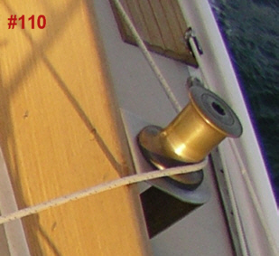
Lacking a stanchion or any other point higher than the coaming board where I could attach a block, an alternative system was explored. This initially involved using the jibsheet winch as a fairlead. See photo #110, which shows the jibsheet making a one-quarter turn around the leeward winch on a starboard tack.
I settled on applying a vang "H" on a transverse section of the jibsheet after seeing a sketch by Tony Heisel in his book A Manual of Single Handed Sailing. Tony Heisel provides a sketch of a sheet-to-tiller configuration that utilizes a quarter turn around the leeward jibsheet winch and then a half turn around the windward winch before securing the jibsheet directly to the tiller. The jibsheet in that case functioned as the control line. No separate control line or vang was shown in that sketch.
I opted to use a separate control line in lieu of tying the jibsheet directly to the tiller. After some experimentation and as a result of concerns with the friction resulting from the jibsheet working on the leeward winch, a jibsheet winch-mounted device was later developed. That device is explored in the Reducing Friction section below.
Even if a lifeline stanchion were available and correctly positioned to attach a turning block, I would have been concerned about placing significant lateral stress on that stanchion given the nature of the deck structure and hull-to-deck seam on the Ariel.
For a discussion of "Augustine" lifeline system can be found on our "Augustine" Photo Page
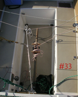
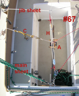
In this jibsheet-to-tiller gear, the jib sheet is lead around the leeward jibsheet winch and then wrapped around the weather side winch and secured to a cleat. See photo #67. One end of a four part tackle (vang "H") is secured by a snap hook to the midpoint (between the winches) of the jib sheet. The other end of the control line attached to vang "H" is run through a series 25 block "G" attached to a pad eye in the center of the rear cockpit bulkhead (where the mainsheet is also attached in this photo). The control line runs from the end of vang "H" through that block and up to a weather side series 25 block "B" on the coaming board and then to steering control box "A" on the tiller.
The system uses tension from the jib sheet to control the tiller, but collects that tension from the transverse section of the jibsheet between the two winches. The tiller senses the tension and makes adjustments accordingly. A counter force is applied by the elastic device "C" at the left side of the photo on the lee rail.
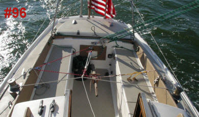
You can see how far off wind we are sailing by the position of the green mainsheet line in photo # 96. To escape from this configuration, all I need to do is unclip the snap hook from the jib sheet, and/or release the two control lines from the steering control box cleats on the tiller. I do not have to be sitting at the rear of the cockpit once this gear is set up. The thin white line running forward to the bottom of the photo is the fall from the tackle. It is controllable from the forward part of the cockpit.
Does it work? Yes it does to a degree, but the action of the jib sheet rubbing against the winch barrel causes a frictional load that makes the gear less sensitive than it needs to be. As a result of this friction, the boat will maintain a more-or-less constant average course off the wind with this gear, but it tends to wander widely from a beam reach to a broad reach due to over correcting, and particularly so when significant swell was striking the hull on the quarter. I have tested this gear under different conditions and various points of sail.
Since this gear can be set up from inside the cockpit, it is a much safer system to activate and deactivate than the cam lever system, which must be placed on the lee side forward of the jib track on the side deck. The narrow lee side of the deck beside the cabin is a spooky place to hang out underway alone, particularly when your hands are busy.
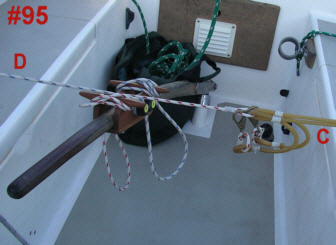
Photo #95 shows a close-up of the steering control box "A", and elastic device "C" in use in a mainsheet-to-tiller gear arrangement. Note that the blue-flecked line "D" indicates that the mainsheet-to-tiller vang is in place. I am displaying this photo here to demonstrate that unused strands of elastic device "C" can be clipped onto the loop in the line attached to elastic device "C" to get them out of the way and keep them from banging on the cockpit seats.
My reason for focusing my efforts on refining this system rather than on refining the cam lever is partially academic and partially in order to make single handing more enjoyable and safer.
Back To The Top
Reducing Friction in The Jibsheet-to-Tiller Gear
To reduce the friction in the system, I attempted to secure a block to the leeward winch, and run the jibsheet through that block and across the cockpit to the windward winch, but when the block selects an appropriate angle so that the sheet will run from the jib track to the windward winch, the sheet rubs against the leeward coaming board. This may not be a problem on another boat, but on the Ariel with its high coaming boards, it is a problem.
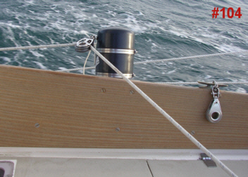
I came up with a basic concept and then spent an hour in my local sprinkler supply store mulling over the alternatives. I developed the device shown in photos #102 and #103 in the "Equipment" section and on photos #104 and #105 in this section.
These devices are built from four (4) inch ABS pipe, end caps, and a coupler designed for use on four (4) inch ABS pipe. A neoprene shim is used so that the device will fit firmly on the top of the jibsheet winches.
The hose clamps on the coupler and the fasteners on the pad eye hold the device together. No glue or cement of any kind was used. Even the neoprene seems to remain in place, although this could be glued in place or secured with the pad eye fasteners if so desired.
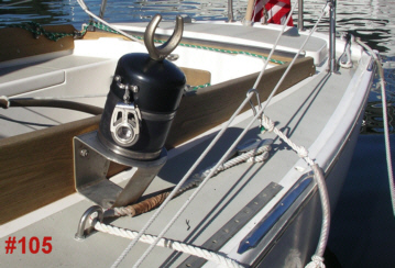
The device does double duty as an oarlock, and was in part designed for that purpose also. Photo #105 shows the oarlock in place at the dock. The oar lock would not be in place under sail.
Testing of this device at sea as part of the above described gear (in lieu of taking a quarter turn around the leeward jibsheet winch) indicates that if the sails are set properly, the boat will track a consistent course with little deviation. Using this refinement eliminates the problematic friction introduced by using the leeward winch as a fairlead.
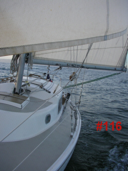
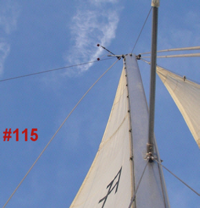
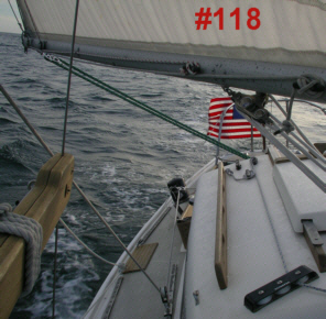
During my first test sail using this device was, I was free to go forward for extended periods while sailing on a broad reach for the first time in my singlehanded sailing career. The boat sailed a steady course on both port and starboard tacks while I took photos including photos #115, #116, and #118.
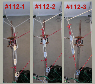
Photo #112 shows three photos taken in succession while standing on the lazarette hatch. This sequence demonstrates the range of motion experienced by the tiller while the gear is in place. The course did not vary more than five (5) degrees off the intended course.
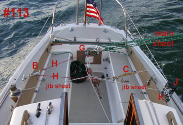
Photo #113 shows the gear at work. The various parts of the system are labelled in this photo.
As with any sheet-to-tiller gear, achieving the correct balance requires both careful adjustment of the gear and correct setting of the sails for the point of sail desired. See photos #116 and #118.
This jib-to-tiller self steering gear will hold a steady course with reasonable variation on headings ranging from a beam reach to a broad reach. In photo #115, the wind indicator held a steady position as shown.
To disconnect this jib-to-tiller gear, all you need to do is release control line "H" and elastic device "C" from the steering control box "A", and unclip control line "H" from the transverse portion of the jibsheet. This can all be done without leaving the cockpit .
Back To The Top

So now having done all that, it's time to go sailing.
Back To The Top
Copyright by Scott Galloway ©. 2005. All rights are reserved.
Back To The Augustine Table of Contents
Back To "This Sailing Page"
Return to Solo Publications Web Index
This page was created by myrmade@solopublications.com
January 19, 2013

 The mainsheet-to-tiller and jibsheet-to-tiller self-steering systems presented here were developed shortly before this page was prepared and posted in 2005. As refinements were made in the self-steering gears featured on this page, I documented those refinements and posted them. I am very interested in the experiences of other Pearson Ariel owners who have successfully experimented with sheet-to-tiller steering. I will appreciate any corrections, additions or other suggestions for improving this web page. Photos or comments on sheet-to-tiller steering systems on Pearson Ariels or on other sailing vessels are welcome.